Popular Sensor Reference Designs
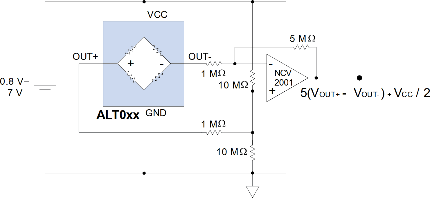
This circuit uses a single-supply op amp. The NCV2001 op amp has a wide bandwidth and can run on as low as a 0.8-volt supply, allowing operation on a 1.5-volt battery. A nanopower op amp such as an MCP6441 can be used for low-power applications. In addition to low power, the MCP6441 has a low gain-bandwidth product, which could eliminate the need for low-pass filtering in some applications.
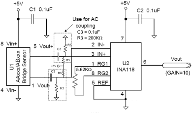
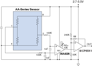
Instrumentation Amplifiers such as the INA118 or INA826 are popular bridge sensor preamplifiers because they reduce chip count and have excellent common-mode rejection ratios without having to match resistors. These amplifiers can run on single or dual supplies, and the INA826 outputs are nearly rail-to-rail. AC coupling can be used for small, dynamic signals such as currency detection.
The circuit above has a gain of 10. The general equation for the output voltage is:
The low-frequency cutoff frequency is set by R3/2 and C3. For the typical values of 200K and 0.1µF, the cutoff frequency is 8 Hz.
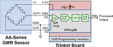
With their high output signals, GMR sensors are easy to interface to inexpensive 8-bit microcontrollers. This circuit uses a Trinket with an eight-pin ATtiny85, which is enough pins to interface to the sensor and provide digital and PWM outputs. The microcontroller can amplify, offset correct, and temperature compensate the outputs. The ATtiny85 is a popular choice because it has an available differential amplifier and a selectable gain of 20; has I2C, PWM, and digital I/O; it has an internal temperature sensor that can be used for temperature compensation in critical applications; and costs less than $1.00. The gain of 20 is ideal for NVE GMR analog sensors. AALSeries sensors, for example, have a maximum output of 45 mV/V, so a gain of 20 provides 900 mV/V, or nearly full scale.
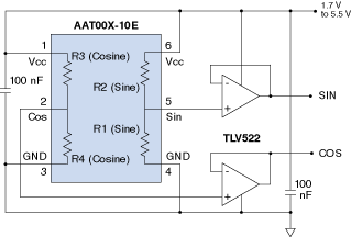
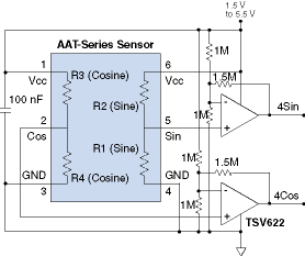
TMR sensors have high output signals, but if amplification is required, a circuit like the one above can be used. The gain of four amplifies the sensor’s typical peak-to-peak signal level of 200 mV/V to 80% of rail-to-rail (one volt/volt), providing more usable signal without risk of saturating the amplifier for a sensor at the high end of the output signal range.
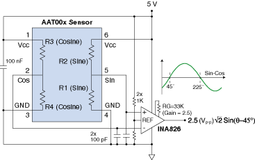
If sine and cosine outputs are not required, a differential amplifier provides a larger signal, more precision, and less temperature dependence than either the sine and cosine output alone. The differential sin-cos voltage has an amplitude of 1.41 times the amplitude of either output, or 226 mV/V. If power consumption is not critical, an instrumentation amplifier can be used to minimize component count as shown in the schematic above. The amplifier gain of three provides a typical peak-to-peak output of 68% of rail-to-rail (one volt/volt). Note that the zero crossing is at 45 degrees, compared to 0 degrees for the Sin output and 90 degrees for the Cos output.
NVE offers AD-Series factory-set GMR Switches, but AA-Series analog sensors can be used for special thresholds or hysteresis, or variable thresholds. In this circuit, the threshold is varied by changing Rg, which sets the gain of the differential amplifier. The 1 megohm resistor sets the threshold hysteresis.
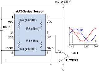
An AAT angle sensor and a simple comparator can be used to provide a precise angular reference point and a one cycle-per-rotation signal. Comparing the sine and cosine outputs is more precise than comparing either to a reference because it corrects for temperature.
In this circuit, the output is high from nominal 45 to 225 degrees, and
low from 225 to 45 degrees. A low voltage, low quiescent current comparator
is used to preserve the AAT sensors’ ultra-low power and wide supply range.
Inherent comparator hysteresis eliminates noise at the transition points. The
TLV3691 comparator hysteresis of 17 mV corresponds to approximately 6 degrees
of hysteresis with a 1.5 V supply. A TS881 or similar comparator has a typical
hysteresis of 4 mV, corresponding to approximately 1.5 angular degrees
of hysteresis.
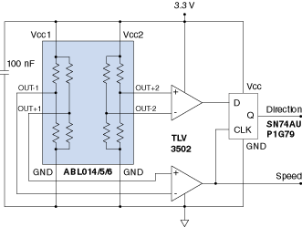
A dual comparator and flip-flop can be used for a precise encoder with direction and speed outputs. Direction is determined by detecting the phasing between the two outputs. The “Speed” output is one cycle per tooth.
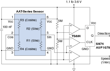
A quad comparator and flip-flop can be used for a precise encoder with direction and speed outputs. Direction is determined by detecting the phasing between the two outputs. The “Speed” output is one cycle per revolution and switches at 45 and 225 degrees. Low-power components and large resistors are used to avoid adding power consumption to low-power applications such as AAT001 interfaces.
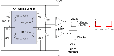
A simple exclusive-OR gate provides a digital signal with two cycles per revolution, and transitions every 90 degrees.
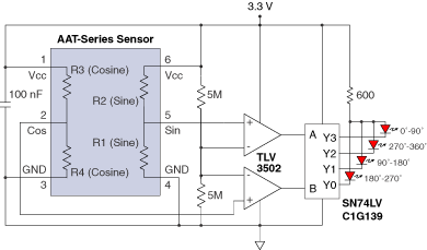
A simple 2-to-4 line decoder provides digital signals indicating the quadrant of rotation.
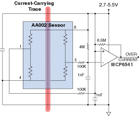
An AA-Series analog sensors over a current trace can be used to detect an overcurrent condition with inherent isolation and no insertion losses. The 100 KΩ and 4 MΩ resistors set the threshold; the 8.5 MΩ feedback resistor sets the comparator hysteresis and therefore the reset threshold.
A 0.09-inch/2.3 millimeter trace width can carry up to about 10 A. An AA003-02E sensor can be used for thresholds of up to 10 A; more sensitive sensors such as the AA002 can be used for lower thresholds.
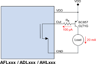
AFL, ADL, and AHT-Series GMR Switches have 100 microamp drive capability, but that can be easily extended using transistors, MOSFETs, or driver ICs. The base resistor is selected so the sensor output current is within the 100 microamp specification, and the transistor’s current gain (420 at room temperature for the device shown) determines the maximum drive current. The circuit above drives up to 20 mA over the full temperature range.
Low-voltage sensors such as AFL-, ADL-, AHL-, ADT-, AHK-, and AHK-Series switches can be inverted using transistors, MOSFETs, or CMOS logic. Transistors and MOSFETs can operate at lower voltage than CMOS logic. The bipolar transistor circuit [left] can be used to the AHLxxx / AHKxxx 0.9-volt minimum opertating voltage. The pullup resistor should be as large as possible to minimize quiescent current while still turning on the transistor. The MOSFET circuit [right] can use larger pullup resistors for less quiescent current. A low-threshold MOSFET, such as an FDN337 with a one-volt maximum Gate-Sourse voltage, can be used.
Three-Wire
Magnetic Proximity Sensor
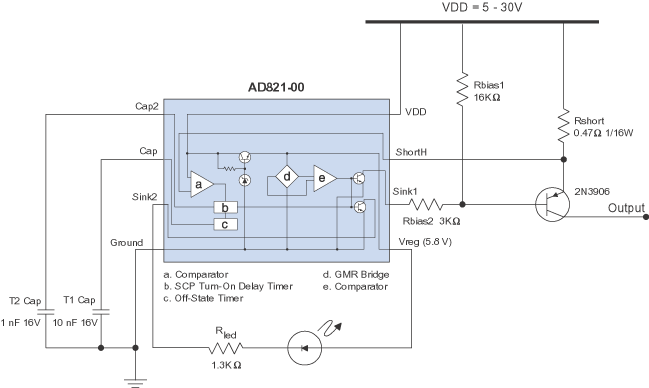
[click image to enlarge]
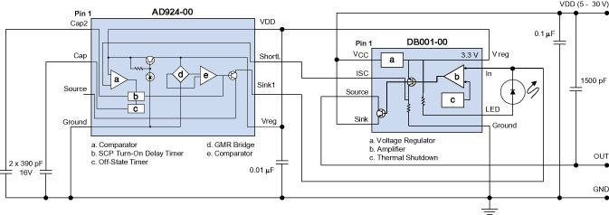
NVEs AD8xx and AD9xx GMR Switches are designed specifically for three-wire interfaces. These parts combine precise magnetic performance with interface electronics, an LED driver, and short-circuit protection. The protection circuitry shuts off the output stage when a short circuit condition detected. After a user-specified time interval, the circuit turns back on. If the short circuit condition persists, the output stage is again shut off and the cycle repeats.
Cap2 delays the startup of the SCP circuitry to avoid triggering the SCP circuitry with normal startup transients. Cap sets the “Off” time of the short-circuit protection circuitry. The voltage across Rshort is monitored by the IC. If this voltage exceeds 145 mV (typical), the short-circuit protection circuitry is activated.
AD8xx/AD9xx-Series sensors are available for current sinking or sourcing outputs and a range of magnetic field operate points. They are available in MSOP-8 packages or bare die for chip-on-board assemblies.
The addition of a DB001-00 Power Switch IC to the previous circuit adds a high-current output, reverse battery protection, and transient protection.
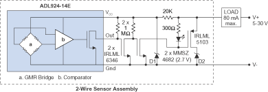
NVE’s ADL-Series sensors are perfect for two-wire applications, because their low supply voltage and low quiescent current provide plenty of design margin.
Two-wire interfaces need to operate over a wide power supply range. With the sensor off, the circuit must draw a minimal residual current, typically less than 1.5 milliamps. With the sensor on, the circuit must provide enough current to drive a significant load such as a motor or solenoid.
In this circuit, when a magnetic field is applied to the sensor, the MOSFETs turn on, turning on the LED and powering the load. With no magnetic field and the sensor off, the residual current of the circuit is the D1 Zener diode bias current plus the sensor quiescent current. The ADL924 quiescent current is negligible, so the residual current is dominated by the Zener current, which is less than 1.5 milliamps. D1 should be a low-current Zener to allow a higher series resistor for minimal residual current. When a magnetic field is applied, the MOSFETs turn on, turning on the LED and powering the load.
Zener diode D1 limits the ADL925 supply voltage with the load unpowered; Zener diode D2 provides enough voltage to power the circuitry when the load is powered.
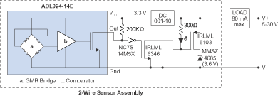
This reference circuit uses an NVE DC001-10 regulator instead of a Zener diode (D1) to provides better regulation and operating latitude over the input voltage range.
The residual current is dominated by the regulator’s quiescent current, which is less than one milliamp and relatively constant over input voltage. This circuit also uses a “TinyLogic” invertor instead of a MOSFET, which eliminates a resistor.
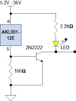
The popular AKL-Series Gear-Tooth Sensors have 4-to-8 mA two-wire interfaces. The interface can be directly used in certain applications, but some application require a three-wire configuration. In the simple circuit above, when the current is 4 mA, the voltage across the 100 ohm resistor is 0.4 V, not enough to turn on the transistor. With 8 mA, the transistor turns on. Note that the supply voltage must be at least 5.2 V to provide the sensor’s 4.5 V minimum Vcc.
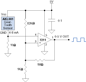
The popular AKL-Series Gear-Tooth Sensors have two-wire current-modulated interfaces. The interface can be directly used in certain applications, but some application require a TTL-compatible digital output. The circuit above uses a simple comparator (7211 or similar) to convert the 4 - 8 mA AKL supply current to a rail-to-rail digital output. The 10 ohm series resistor is small enough to ensure the AKL Vcc voltage is above its 4.5 V minimum with a 4.75 - 5.25 V supply. The 1KΩ and 82KΩ resistors set a comparator threshold between 4 and 8 mA, and the 1 megohm resistor provides hysteresis to enhance noise immunity.
AKL-Series Gear-Tooth Sensors feature a 50% duty cycle and DC (zero-speed) operation.
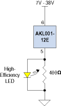
Two-wire interface AKL-Series digital Gear-Tooth Sensors have 4-to-8 mA output, which is enough to drive an LED. However, the 4 mA “off” current is enough to illuminate an LED if it is simply connected in series with the supply or ground. In the circuit above, the 400 ohm resistor draws slightly more than 4 mA at the LED turn-on voltage of 1.8 V. This ensures there is not enough current to turn on the LED with a 4 mA output, but enough to illuminate a high-efficiency LED when the sensor output is 8 mA. This circuit requires no external active components. Another advantage of this circuit is the LED brightness is independent of supply voltage. Note that the supply voltage must be at least 7 V to provide the sensor’s 4.5 V minimum Vcc.
