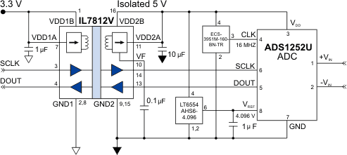
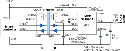
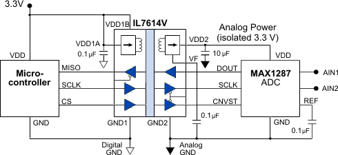
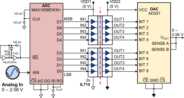
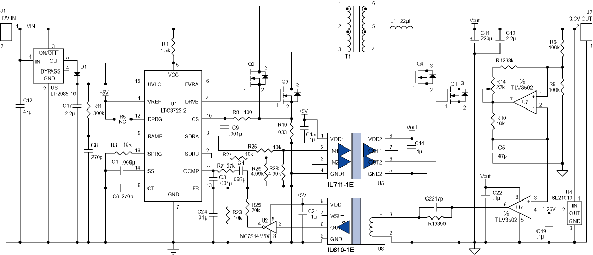
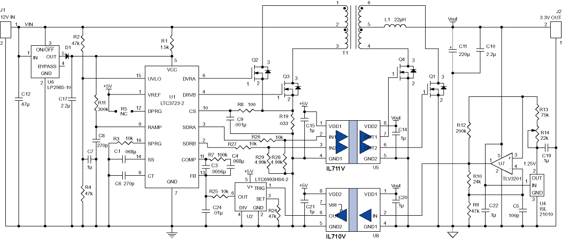
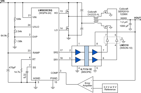
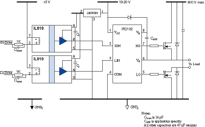
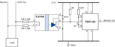
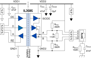
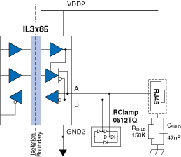
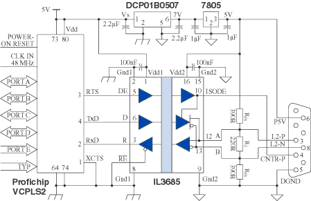
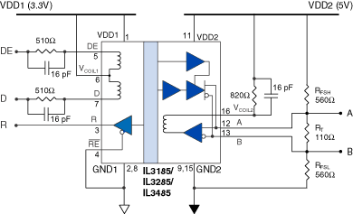
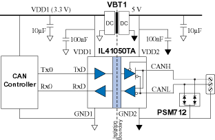
| Popular Isolator Reference Designs Just two channels are needed for ADCs with two-wire serial interfaces and no chip-selects or other interface lines. The IL7812V’s boost convertor can power classic five-volt ADCs such as the ADS1252U, and allows analog inputs above the 3.3-volt system supply for 3.3 to 5-volt ADCs such as the LTC2400-series: This circuit takes advantage of the “two-wire interface mode” of an MCP3918 analog front end for shunt-based current sensing. Unlike most optocouplers, the IL7612V isolator section is fast enough for the front-end’s 20 MHz high-speed SPI: An eight-bit A-to-D convertor measures the voltage, the data are isolated by a pair of four-channel isolators, then converted back to analog by a D-to-A convertor. This circuit uses a simple astable oscillator as a sampling clock, with an ADC sampling rate over 100 kS/s. Since NVE isolators have rail-to-rail outputs, an inexpensive R/2R network can replace the DAC in some applications. A three-channel isolator is ideal for half-duplex SPI: NVE isolators are ideal for isolating parallel data convertors such as ADCs and DACs. Isolation prevents ground loops and enhances safety. This reference design is for high-speed, asynchronous analog-to-analog isolation with just a few chips, no microprocessor, and no software: An eight-bit A-to-D convertor measures the voltage, the data are isolated by a pair of four-channel isolators, then converted back to analog by a D-to-A convertor. This circuit uses a simple astable oscillator as a sampling clock, with an ADC sampling rate over 100 kS/s. Since NVE isolators have rail-to-rail outputs, an inexpensive R/2R network can replace the DAC in some applications. This circuit is for an approximately 2.5W switch-mode power supply. An IL711-1E isolates the synchronous rectification. A simple pulse-width modulator digitizes the output voltage and an inherently failsafe IL610-1 isolator provides isolated feedback for the output voltage. The IL610-1 replaces the linear optocoupler typically used for this purpose, eliminated a major reliability problem. The MSOP-8 isolators minimize board area. The IL711’s 0.3 ns pulse-width distortion and 100 ps jitter improve precision, minimize MOSFET dead time, and maximize system efficiency. This circuit is for an approximately 2.5W switch-mode power supply. An IL711V-1E MSOP 2.5 kV Isolator isolates the synchronous rectification. A simple voltage-to-frequency convertor digitizes the output voltage, and an IL710V-1 provides isolated feedback for the output voltage. A one shot serves as a frequency-to-voltage convertor to provide output voltage feedback. The IL710V-1 replaces the linear optocoupler typically used for this purpose, eliminated a major reliability problem. The MSOP isolators minimize board area. The isolators' pulse-width distortion and 100 ps jitter improve precision, minimize MOSFET dead time, and maximize system efficiency. Low EMI, transient immunity of 50 kV/µs, and barrier life of 44000 years make IL700-Series isolators ideal for this application. This circuit is for an approximately 100 W quarter-brick-scale power supply. An IL711V-1E isolates the LM5035CSQ PWM Controller from the LM5110 MOSFET gate driver for synchronous rectification. All of the key ICs in this reference design are small. The LM5035CSQ is a WQFN-24; the LM5110 is available in a WSON-10, and the IL711 in an MSOP8). IL711V-1E provides two-channels and full 2.5 kV isolation in an ultraminiature MSOP-8 package. Alternatively, the wide-body IL711VE provides 5 kV isolation and best-in-class 1 kV Working Voltage in a true 8 mm creepage package. The IL711’s 0.3 ns pulse-width distortion and 100 ps jitter improve precision, minimize MOSFET dead time, and maximize system efficiency. Low EMI, transient immunity of 50 kV/µs, and barrier life of 44000 years make IsoLoop isolators ideal for this application. The fail-safe output (logic high output for zero coil current) of IL600 Isolators ensures the power FETs will be off on power-up. The IL600 inputs can be configured for inverting or non-inverting operation (see IL600 Product Data Sheet). The IL600 Isolators provide 2.5 kVrms isolation (1 minute), and 20 kV/µs transient immunity. The wide input voltage range of IL600 Isolators allows connection to line voltage through current-limiting resistors. Unlike optocouplers, input voltage can reverse without damaging the inputs. In this illustrative circuit, “Monitor Out” goes low when line voltage drops significantly. The 74HC123 monostable converts the 60 Hz isolator output to a monitor signal. Faster and longer networks should be be terminated. Reflections are minimized by terminating both ends of the bus but not every node. Two 120 ohm termination resistors (on each end of the bus) are used to match a 60 ohm cable impedance. With terminated networks the differential voltage across the conductor pair will be close to zero with no active drivers. In this case, the idle bus is indeterminate and susceptible to noise. External fail-safe biasing resistors (RFS-EXT) at one end of the bus ensure fail-safe operation with a terminated bus. Biasing should provide at least 200 mV across the conductor pair to meet the RS-485 input sensitivity specification. The more loads on the bus, the lower the required values of the biasing resistors. The reference design has a 120 ohm termination resistor and 560 ohm biasing resistors for fail-safe operation for up to four Unit Loads. IL3000-Series transceivers can withstand ±7 kV bus ESD, and TVS diodes can provide additional protection if necessary. The RClamp0512TQ provides ±30 kV ESD protection with low capacitance and the appropriate clamping voltage. The 220 ohm termination resistor, along with another 220 ohm resistor and the other end of the bus, matches the bus impedance to minimize reflections. The 390 ohm “fail-safe” resistors guarantee a known state with no active transceivers. Bypass capacitors should be placed as close as possible to the appropriate IC. NVE’s unique passive-input isolated transceivers have current-mode inputs for maximum flexibility. A reference design for a 3.3 V controller and 5 volt bus is shown above. NVE’s passive-input single-chip isolated RS-485 transceivers allow low-cost repeaters. Parts are available in 0.3" and 0.15" 16-pin SOIC packages. Isolating the input to a USB controller (rather than the bus lines) requires fewer isolation channels, and is therefore usually the simplest solution as shown in this reference design: 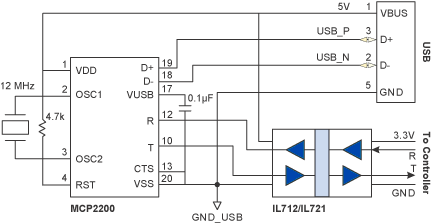 The Microchip MCP2200 is a USB 2.0 to UART Protocol Converter. The IL712/IL721 Series are best-in-class bidirectional isolators with a remarkable 100 ps of jitter, and parts are available in unique MSOPs to reduce board space. The IL41050 single-chip isolated CAN transceiver provides an isolated CAN interface in a single chip. The isolator operates on the 3.3 V microcontroller power supply, and a low-cost dc-dc convertor provides 5 V to power the bus side. The IL41050 can withstand 200 V transients on the bus; the PSM712 provides additional ESD protection if necessary. Designed for harsh CAN and DeviceNet environments, IL41050 transceivers have a -55 to +125°C operating range, transmit data dominant time-out, bus pin transient protection, thermal shutdown protection, short-circuit protection, 2,500 V isolation, and typical transient immunity of 30 kV/µs. Unique edge-triggered inputs improve noise performance. An innovative nonvolatile programmable power-up feature prevents unstable nodes.
A state that needs to be present at node power up can be programmed at the last
power down. For example if a CAN node is required to “pulse” dominant at power
up, TxD can be sent low by the controller immediately prior to power down. When
power is resumed, the node will immediately go dominant allowing self-check code
in the microcontroller to verify node operation. If desired, the node can also
power up silently by presetting the TxD line high at power down. At the next power
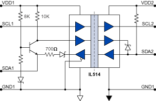
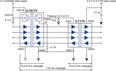
on, the IL41050 will remain silent, awaiting a dominant state from the bus. A three-channel isolator and some simple components allow bidirectional isolation of I²C. Combining two guaranteed eight-millimeter creepage packages in series provides more than 16 millimeter creepage in a small, convenient form factor. This meets the requirements for 500 VRMS working voltage under IEC 60601. |
