|
Daylight
Saving Time
ends Sunday, November 1. “Rotate” your clocks back an hour.
|
|
|
|
NVE will be closed
Thursday and Friday, November 26 and 27 for the Thanksgiving holiday.
We will be open Veterans’ Day (November 11). |
|
|
|
|
|
 |
|
|
Cylinder
Position Sensors |
|
|
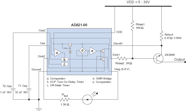
NVE AD8xx/AD9xx
GMR Switches are complete Cylinder
Position (CPS) sensor solutions, including voltage regulators, LED drivers, and
short-circuit protection.
Here's a reference circuit:

When the magnet is detected, the sensor bridge activates, the LED turns ON, and
the load is powered.
If the output is shorted, the voltage across this shunt resistor exceeds the circuit’s
145 mV short-circuit threshold. With a 0.47 ohm shunt resistor, the
threshold is about 300 mA.
The output will cycle as long as the short circuit persists, preventing damage
to the part. Short-circuit cycle times are set by external capacitors.
Here’s a demonstration:
|
 |
|
|
Halloween
Application Corner |
|
|

2-Wire
Interfaces Don’t Have to Be Scary
Two-wire sensor interfaces are right up there with bats, ghosts, and goblins as
things we'd rather not deal with.
Two-wire interfaces need to operate over a wide power supply range.
With the sensor off, the circuit must draw a minimal residual current, typically
in the range of 1.5 mA. With the sensor on, the circuit must provide enough
current to drive a significant load such as a motor or solenoid.
NVE’s ADL-Series
sensors take the scare out of two-wire, because their low supply voltage
and low quiescent current provide plenty of design margin.
Here’s a simple reference
circuit:
 Two-Wire Reference Circuit With Zener Diodes
In this circuit, when a magnetic field is applied to the sensor, the MOSFETs turn
on, turning on the LED and powering the load. With no magnetic field and the sensor
off, the residual current of the circuit is the D1 Zener diode bias current plus
the sensor quiescent current. The ADL924 quiescent current is negligible, so the
residual current is dominated by the Zener current, which is less than 1.5 mA.
D1 should be a low-current Zener to allow a higher series resistor for minimal
residual current. When a magnetic field is applied, the MOSFETs turn on, turning
on the LED and powering the load.
Zener diode D1 limits the ADL925 supply voltage with the load unpowered; Zener
diode D2 provides enough voltage to power the circuitry when the load is powered.
This
circuit uses an NVE DC001-10
regulator instead of a Zener diode (D1) to provides better regulation and operating
latitude over the input voltage range:
 Two-Wire Reference Circuit Using a Voltage Regulator
The residual current is dominated by the regulator’s quiescent current, which
is less than 1 mA and relatively constant over input voltage. This
circuit also uses an “TinyLogic” invertor instead of a MOSFET, which
eliminates a resistor.
 2-Wire
Interface video (03:30) > 2-Wire
Interface video (03:30) > |
|


